Home
Products
Physics research field


Type of experiment


Detector type


Behind the science
Tech in a nutshell
United Kingdom (EN)
Select your region or country.


Key benefits
Photocathode: How it works, and available options
A photocathode is a thin, photosensitive film deposited on a surface inside the vacuum photomultiplier tube (PMT), just beyond the input window. When light enters through the input window, it interacts with the photocathode, where photons are converted into photoelectrons via the photoelectric effect. The number of photoelectrons produced is directly proportional to the number of incident photons.
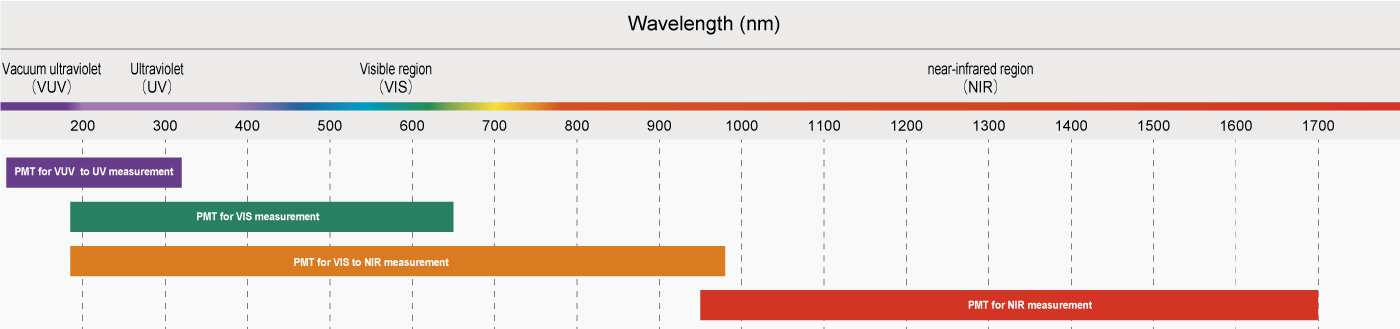
The choice of photocathode material significantly impacts the spectral sensitivity of the PMT. Materials used include various alkalis and III-V semiconductors. Alongside the chosen window material, the photocathode material determines the PMT’s wavelength sensitivity. For instance, bialkali photocathodes are sensitive in the UV and visible regions, whereas GaAsP photocathodes exhibit no UV sensitivity but offer higher performance in the visible range.
Hamamatsu Photonics has also developed photocathodes with materials for extreme wavelengths. For example, Cs-I and Cs-Te photocathodes, which are solar-blind, enable UV detection (down to 115 nm). In contrast, Hamamatsu also manufactures NIR-PMTs, which utilize advanced III-V semiconductor photocathodes (e.g., GaAs, InGaAs, InGaAsP, etc.). These can be sensitive up to 1700 nm.
Transmission vs reflection mode photocathodes
Beyond wavelength sensitivity, photocathodes can be classified by photoelectron emission processes:
Transmission mode are semitransparent and are typically deposited directly on the inner side of the input window. The emitted photoelectrons travel in the same direction as the incident light (e.g. in head-on PMTs).
Reflection mode are opaque and typically formed on a metal plate within the vacuum tube, facing the input window. Photoelectrons are emitted in the opposite direction to the incident light.
Transmission and reflection mode photocathodes of the same material can also differ in spectral response range.
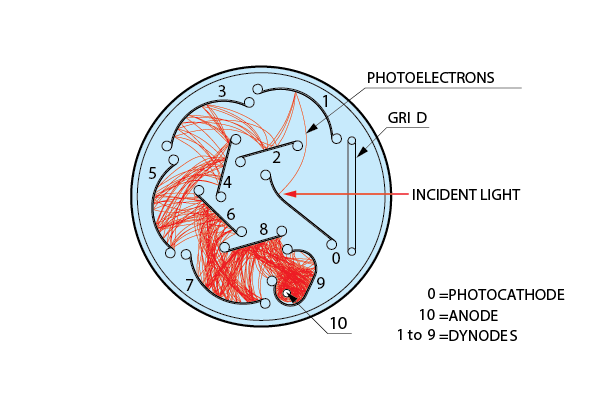
Fig. 1: Circular-cage type
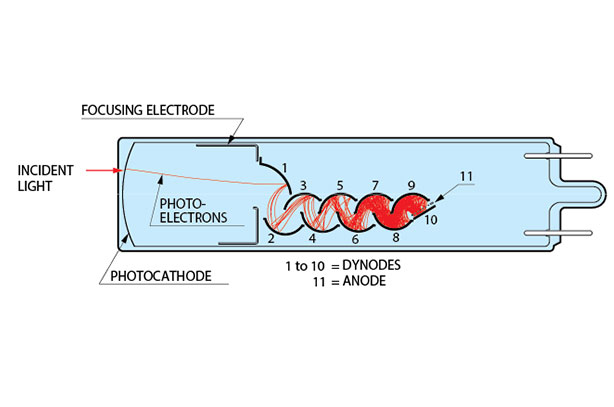
Fig. 2: Linear focus type
A comprehensive guide on spectral response ranges based on photocathode materials, emission modes, and window material combinations can be found here: PMT_handbook_v4E.pdf (pages 34 to 37).
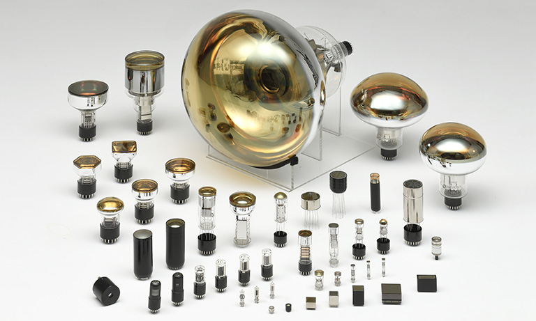
A wide range of shapes and sizes
In addition, photocathodes can be fabricated in various shapes and sizes, offering flexible dimensions due to their thin-film deposition process. We manufacture a wide range of PMT sizes (from a tiny ½” all the way up to 20” tubes) and shapes (including circular, square, and hexagonal options, with flat or curved detection areas.
Transit time spread: Definition and performance
Transit Time Spread (TTS) refers to the variation in the time it takes for an electron to travel from the photocathode to the anode within a PMT. It directly impacts the timing precision of the PMT, affecting applications requiring high temporal resolution (see Fig. 3 and 4).
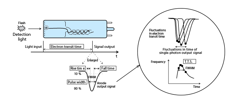
Fig. 3: Concept of time characteristics
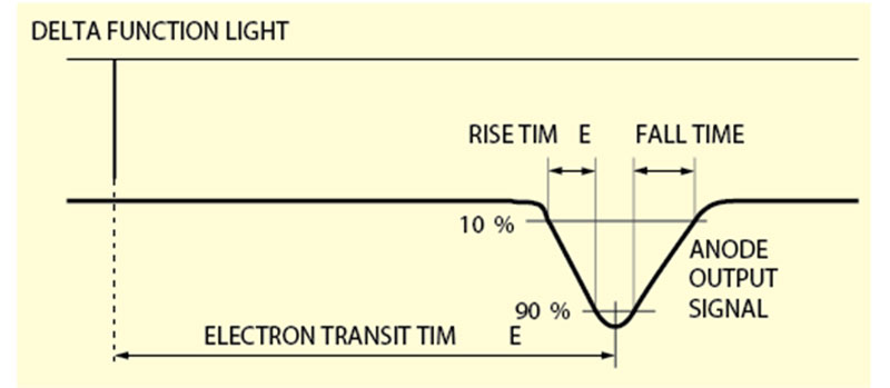
Fig. 4: Definitions of rise/fall times and election transit time
How does TTS affect photon detection accuracy?
TTS impacts both accuracy and resolution of photon detection:
- Temporal resolution: A larger TTS results in greater uncertainty in the timing measurement, which can blur the distinction between closely spaced photon events.
- Accuracy: High TTS can lead to inaccurate time measurements, especially in applications where precise timing is crucial, such as time-correlated single photon counting (TCSPC) and time-of-flight measurements.
Factors contributing to TTS variability
Several factors influence the variation in TTS, including:
- Photon arrival position: Variations in where the photon hits the photocathode can cause differences in the electron travel time.
- Dynode structure: The design and spacing of dynodes can affect the electron multiplication process and transit time.
- Voltage fluctuations: Variations in the high voltages applied to the PMT can influence electron acceleration and time spread.
- Temperature dependence: Temperature changes can affect the PMT's performance, including TTS.
How is TTS measured and quantified
TTS is typically quantified using the full width at half maximum (FWHM) of the timing distribution of photon arrival times. This is determined through:
- Timing calibration: Using a known light source and precise timing electronics
- Manufacturer specifications: TTS is provided in datasheets, often measured in nanoseconds (ns).
PMTs with superior TTS performance
Certain PMTs offer superior TTS performance due to their design features:
- High-gain PMTs: Often used in specialized applications for their ability to provide precise timing.
- Low-noise PMTs: Designed to minimize electronic noise and improve timing accuracy.
Applications requiring low TTS
Low TTS is critical for applications such as:
- Time-Correlated Single Photon Counting (TCSPC): Essential for precise photon arrival measurements.
- Time-of-Flight (TOF) mass spectrometry: Requires accurate particle timing for mass determination.
- High-energy physics experiments: Demands precise timing of particle detections.
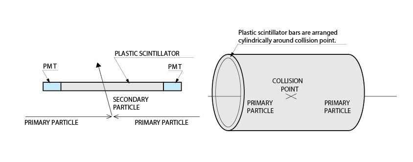
Fig. 5: Detector and overall schematic of a TOF counter
Trade-offs in optimizing TTS
Improving TTS performance may involve trade-offs:
- Cost: PMTs with better TTS performance can be more expensive due to advanced manufacturing techniques and materials.
- Complexity: Achieving optimal TTS may require more complex electronics and calibration, increasing system complexity.
- Size and power: High-performance PMTs might require more space or power for stable operation, which can be a consideration in some setups.
PMTs vs MPPC®s (SiPMs) in TTS performance
| TTS feature | PMT | MPPC |
|---|---|---|
| Advantages | Generally offers lower TTS due to high gain and low noise characteristics. | Compact and operate at lower voltages. Recent developments have improved their TTS performance. |
| Disadvantages | Requires high-voltage operation. | Historically, it had higher TTS, but technological improvements are closing this gap. |
Hamamatsu continuously enhances TTS performance through advancements in both PMT and MPPC technologies. Their optimized electron multiplication mechanisms and dynode structures improve PMT designs, while enhanced electronics stabilize high-voltage operation for greater timing precision. Additionally, ongoing developments in MPPC technology focus on reducing timing spread, making them increasingly competitive with PMTs.
PMT lifetime and response recovery
PMTs are highly sensitive to low light across the UV, visible, and NIR ranges spectrum, amplifying signals by up to 10 million times. Their operational lifetime typically extends for thousands of hours, though factors such as operating conditions and exposure to high-intensity light can accelerate degradation.
PMT aging and recovery
Aging in PMTs manifests as a gradual decrease in sensitivity and an increase in noise levels, often due to the slow degradation of the photocathode and the dynodes. Factors influencing this include:
- Exposure to high-intensity light can accelerate photocathode degradation.
- Operating at high voltages or temperatures can also shorten the lifespan of a PMT.
Recovery from aging is sometimes possible through:
- Annealing: Controlled heating for a certain period to rejuvenate the photocathode material.
- Preventative measures: Using appropriate filters to block out high-energy photons that could damage the photocathode and maintaining a stable operating environment.
Performance improvements in Hamamatsu PMTs
Research into new materials and technologies continues to improve PMT longevity and performance. For example, advancements in photocathode materials have led to increased resistance to aging effects. Recent R&D at Hamamatsu has resulted in significant improvement in response recovery, particularly in high-energy experiments where PMTs must withstand high anode charge accumulation.
Fig. 6 & 7: Long term aging test of the new PMTs for the HL-LHC ATLAS hadron calorimeter upgrade, F. Scuri, on behalf of the ATLAS Tile Calorimeter System, IstitutoNazionale di Fisica Nucleare - Sezione di Pisa, Italy.
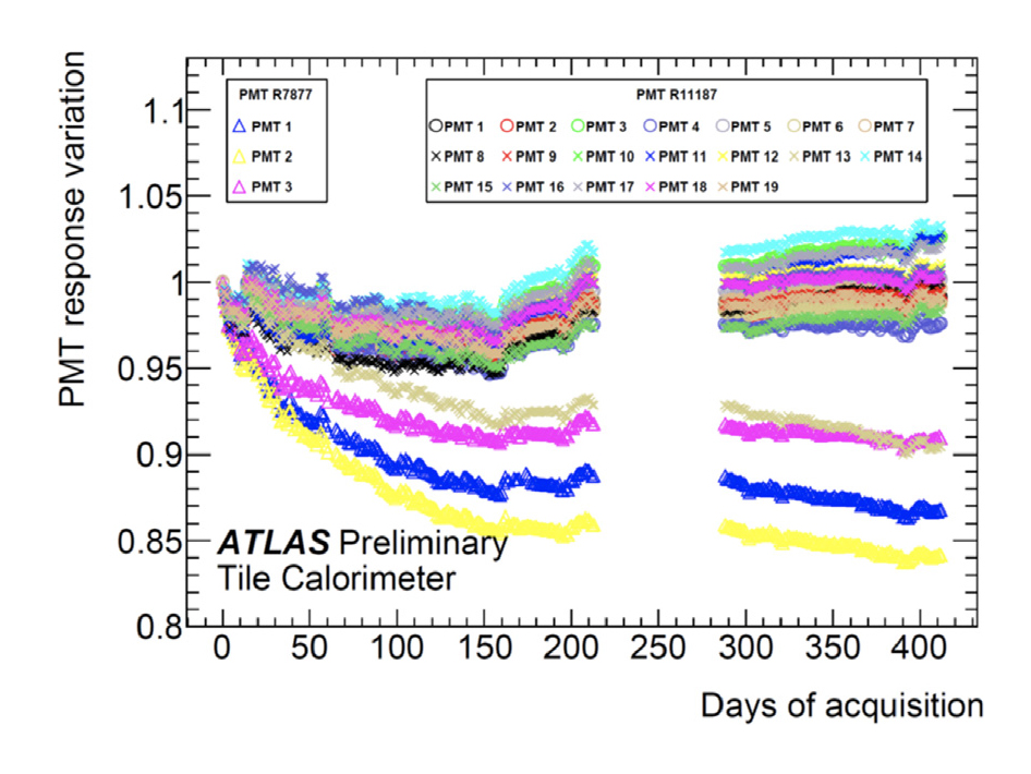
Fig. 6: Variation of the PMT response as a function of time
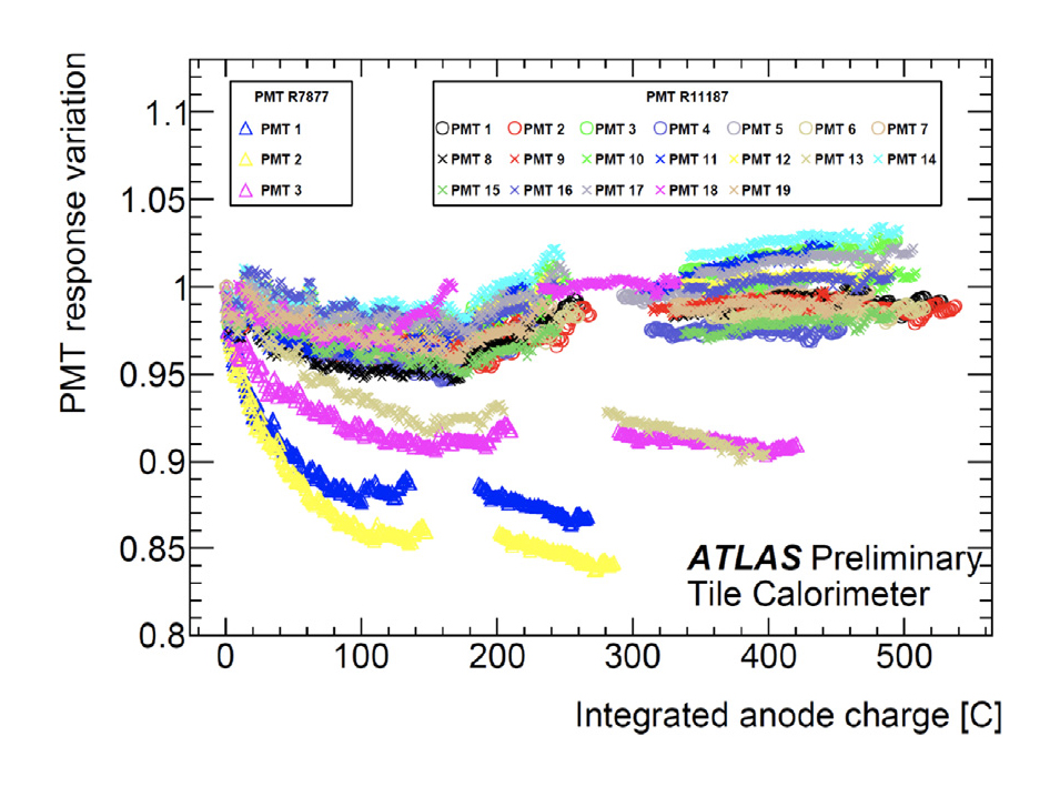
Fig. 7: Variation of the PMT response as a function of the ubtegrated anode charge
Data from the ATLAS Calorimeter on the R7877 PMT highlights:
- Newer PMT models exhibited a response loss of no more than 5% in all but one tested sample, while older models experienced losses of 10% or greater.
- The initial response decline was more severe in older PMT models (The left box with Triangle marks are older PMTs). Variability in response evolution was higher in older models, whereas newer models demonstrated greater consistency and stability over time.
These results show the superior response stability of newer Hamamatsu PMTs, particularly in high-radiation environments. The improved materials and design optimizations contribute to reduced performance degradation, making modern PMTs more reliable for long-term applications.
Future directions
Advancements in photocathode technology, TTS optimization, and response recovery continue to enhance PMT performance. Hamamatsu remains at the forefront of PMT innovation, ensuring these detectors maintain their relevance in scientific and industrial applications requiring high sensitivity, precision timing, and broad spectral coverage.
- Confirmation
-
It looks like you're in the . If this is not your location, please select the correct region or country below.
You're headed to Hamamatsu Photonics website for GB (English). If you want to view an other country's site, the optimized information will be provided by selecting options below.
In order to use this website comfortably, we use cookies. For cookie details please see our cookie policy.
- Cookie Policy
-
This website or its third-party tools use cookies, which are necessary to its functioning and required to achieve the purposes illustrated in this cookie policy. By closing the cookie warning banner, scrolling the page, clicking a link or continuing to browse otherwise, you agree to the use of cookies.
Hamamatsu uses cookies in order to enhance your experience on our website and ensure that our website functions.
You can visit this page at any time to learn more about cookies, get the most up to date information on how we use cookies and manage your cookie settings. We will not use cookies for any purpose other than the ones stated, but please note that we reserve the right to update our cookies.
1. What are cookies?
For modern websites to work according to visitor’s expectations, they need to collect certain basic information about visitors. To do this, a site will create small text files which are placed on visitor’s devices (computer or mobile) - these files are known as cookies when you access a website. Cookies are used in order to make websites function and work efficiently. Cookies are uniquely assigned to each visitor and can only be read by a web server in the domain that issued the cookie to the visitor. Cookies cannot be used to run programs or deliver viruses to a visitor’s device.
Cookies do various jobs which make the visitor’s experience of the internet much smoother and more interactive. For instance, cookies are used to remember the visitor’s preferences on sites they visit often, to remember language preference and to help navigate between pages more efficiently. Much, though not all, of the data collected is anonymous, though some of it is designed to detect browsing patterns and approximate geographical location to improve the visitor experience.
Certain type of cookies may require the data subject’s consent before storing them on the computer.
2. What are the different types of cookies?
This website uses two types of cookies:
- First party cookies. For our website, the first party cookies are controlled and maintained by Hamamatsu. No other parties have access to these cookies.
- Third party cookies. These cookies are implemented by organizations outside Hamamatsu. We do not have access to the data in these cookies, but we use these cookies to improve the overall website experience.
3. How do we use cookies?
This website uses cookies for following purposes:
- Certain cookies are necessary for our website to function. These are strictly necessary cookies and are required to enable website access, support navigation or provide relevant content. These cookies direct you to the correct region or country, and support security and ecommerce. Strictly necessary cookies also enforce your privacy preferences. Without these strictly necessary cookies, much of our website will not function.
- Analytics cookies are used to track website usage. This data enables us to improve our website usability, performance and website administration. In our analytics cookies, we do not store any personal identifying information.
- Functionality cookies. These are used to recognize you when you return to our website. This enables us to personalize our content for you, greet you by name and remember your preferences (for example, your choice of language or region).
- These cookies record your visit to our website, the pages you have visited and the links you have followed. We will use this information to make our website and the advertising displayed on it more relevant to your interests. We may also share this information with third parties for this purpose.
Cookies help us help you. Through the use of cookies, we learn what is important to our visitors and we develop and enhance website content and functionality to support your experience. Much of our website can be accessed if cookies are disabled, however certain website functions may not work. And, we believe your current and future visits will be enhanced if cookies are enabled.
4. Which cookies do we use?
There are two ways to manage cookie preferences.
- You can set your cookie preferences on your device or in your browser.
- You can set your cookie preferences at the website level.
If you don’t want to receive cookies, you can modify your browser so that it notifies you when cookies are sent to it or you can refuse cookies altogether. You can also delete cookies that have already been set.
If you wish to restrict or block web browser cookies which are set on your device then you can do this through your browser settings; the Help function within your browser should tell you how. Alternatively, you may wish to visit www.aboutcookies.org, which contains comprehensive information on how to do this on a wide variety of desktop browsers.
5. What are Internet tags and how do we use them with cookies?
Occasionally, we may use internet tags (also known as action tags, single-pixel GIFs, clear GIFs, invisible GIFs and 1-by-1 GIFs) at this site and may deploy these tags/cookies through a third-party advertising partner or a web analytical service partner which may be located and store the respective information (including your IP-address) in a foreign country. These tags/cookies are placed on both online advertisements that bring users to this site and on different pages of this site. We use this technology to measure the visitors' responses to our sites and the effectiveness of our advertising campaigns (including how many times a page is opened and which information is consulted) as well as to evaluate your use of this website. The third-party partner or the web analytical service partner may be able to collect data about visitors to our and other sites because of these internet tags/cookies, may compose reports regarding the website’s activity for us and may provide further services which are related to the use of the website and the internet. They may provide such information to other parties if there is a legal requirement that they do so, or if they hire the other parties to process information on their behalf.
If you would like more information about web tags and cookies associated with on-line advertising or to opt-out of third-party collection of this information, please visit the Network Advertising Initiative website http://www.networkadvertising.org.
6. Analytics and Advertisement Cookies
We use third-party cookies (such as Google Analytics) to track visitors on our website, to get reports about how visitors use the website and to inform, optimize and serve ads based on someone's past visits to our website.
You may opt-out of Google Analytics cookies by the websites provided by Google:
https://tools.google.com/dlpage/gaoptout?hl=en
As provided in this Privacy Policy (Article 5), you can learn more about opt-out cookies by the website provided by Network Advertising Initiative:
http://www.networkadvertising.org
We inform you that in such case you will not be able to wholly use all functions of our website.
Close